Getting the most out of a V-dipole
Towards the end of a METEOR acquisition with the wonderfully simple V-dipole, I tried to improve signal by turning the antenna. That helped a bit, but I was surprised to find that lifting the antenna up changed the signal a lot. And it wasn’t just the higher the better: some heights gave better signal than others. Clearly, something more complicated was going on.
In this post, I’ll try to understand what happened.
Seeing further with METEOR
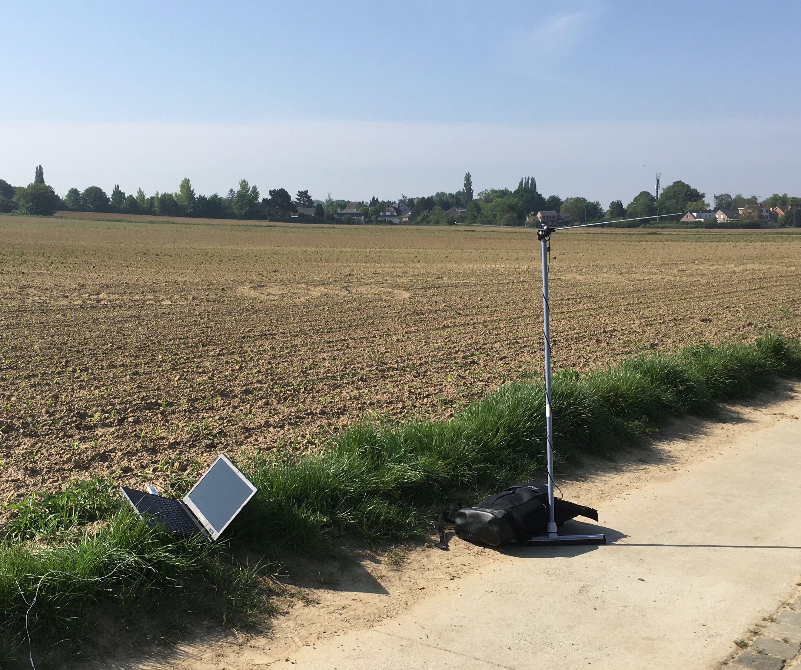
When I use the V-dipole from my apartment, the field of view is quite limited due to surrounding high buildings. So, I tried placing the antenna out in a field with a pretty good view of the horizon. The signal from METEOR indeed appeared at quite low elevation (about 10°), which is much better than at home (25° or so).
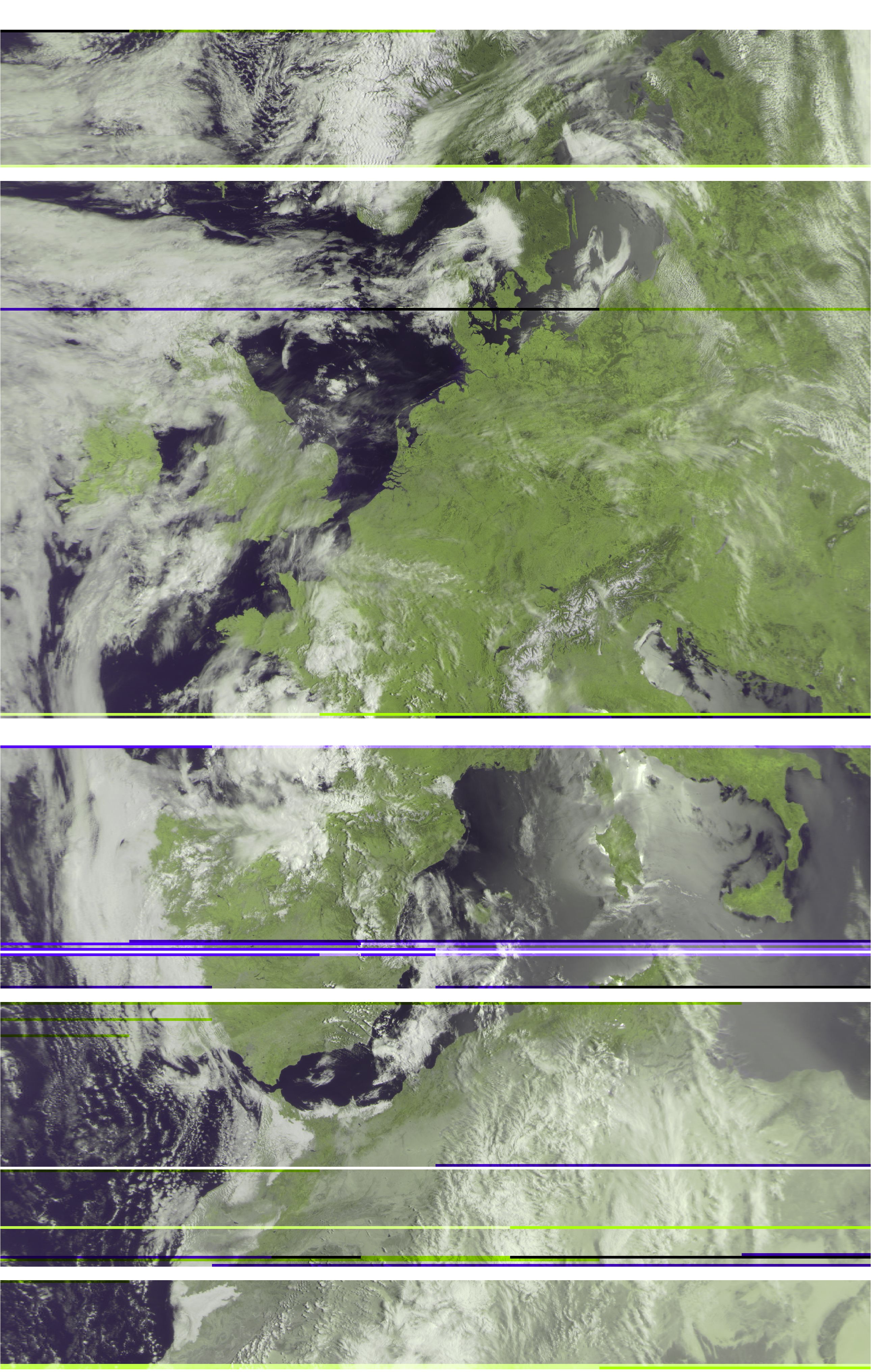
The recording definitely wasn’t perfect (the antenna fell over during the satellite pass…), but it’s the first time I could see a nice chunk of Africa. If I hadn’t changed the height of the dipole, however, there wouldn’t have been a strong enough signal.
Understanding an antenna
Reading through the ARRL Antenna handbook, I noticed that I hadn’t thought much about the workings of the V-dipole. I really like the idea of using the cheap telescopic antenna from the RTL-SDR kit. So instead of buying a more expensive directional antenna like a Yagi or this turnstile antenna, I’ll first try to get the most out of the V-dipole.
To understand it better, and to find out how to use it in the best way possible, I simulated the radiation pattern. Specifically, I’d like to know what’s the best V-angle, and how high should the dipole be above ground?
Simulating an antenna
In order to simulate the antenna, I used NEC. More specifically, since I enjoy working with Python, I used PyNEC. It didn’t compile straight away on my Mac running OS X, but I did get it to work eventually.
In NEC, the elements of an antenna and its surroundings are defined using cards. Apparently, the original NEC was written in the 1970s, and these cards are to be taken literally, as the user needed to enter the antenna parameters on actual punch cards.
The fundamental element in NEC to describe an antenna is the wire, which is straight. To model the V-dipole, one solution is to break it in three parts: a short connector element in the middle, where the excitation will be applied, and two quarter-wave wires extending at an angle. There’s an interesting discussion about the different possibilities to model the V-dipole here.
Here is a schematic of the V-dipole model I used, with the excitation source shown as a red circle.

$L/2$ is the length of each leg, the connector element was taken to be 1 cm wide, and the V-dipole angle $\alpha$ was defined as shown above. I will optimize $L$ for resonance, hence it will be close to half a wavelength (a quarter wave length per leg).
To simulate the ground underneath the antenna, I used the following parameters: dielectric constant 13, conductivity 0.006 S/m.
Optimizing the antenna leg length and V-angle
Since I use the V-dipole for receiving NOAA APT and METEOR LRPT, and preferring the latter, I optimized the leg length $L/2$ and V-angle by minimizing the VSWR for $50 \Omega$ impedance at 137.1 MHz. The RTL-SDR v3 has $50 \Omega$ input impedance according to the datasheet, and so does my SMA cable.
I ran the optimization for an antenna at $\lambda/2$ above ground, or 1.09 m. The leg length after optimization was 53.1 cm, and the angle 39.5°, resulting in a simulated VSWR of 1.0.
Using the V-angle at 30° as in the RTL-SDR blog post, gives a VSWR 1.25, which is still good I guess.
Radiation patterns
To get an idea of the angles for which the V-dipole works best, I computed the antenna’s radiation pattern in different conditions (V-angle, height above ground). In the plots below, azimuth is the angle in the xy-plane measured from the x-axis, and elevation is the angle with the z-axis.
The effect of V-dipole angle
To get started, let’s analyze the radiation patterns when the antenna is at half a wave (1.09 m) above ground.
Radiation pattern vs azimuth
Gain [dB], 30° elevation, $\lambda/2$ above ground (1.09 m)

This plot shows the effect of the V-angle: at 0°, the antenna is a regular horizontal dipole, which has a null along the x-axis. The null isn’t very deep due to the ground not being a perfect conductor. Increasing the V-angle also fills in the null, but the effect of imperfect ground is more pronounced.
Radiation pattern vs elevation
Gain [dB], 90° azimuth, $\lambda/2$ above ground (1.09 m)

From this radiation pattern, we can see that at roughly 8° elevation, the antenna has 0 dB of gain, and reaches a maximum around 30° of elevation. When the satellite is directly overhead, the gain decreases quite a bit, down to -5 dB (30%) when it is directly overhead. Since the satellite’s signal doesn’t need to travel very far when it is directly overhead, it is much stronger, and the lower gain is not an issue. The effect of the V-angle seems quite small in this view of the radiation pattern.
The effect of height above ground
Now let’s see what happens when we place the 30° V-dipole at different heights above ground?
Radiation pattern vs azimuth
Gain [dB], 30° elevation, $\lambda/2$ above average ground

Radiation pattern vs elevation

That’s a very busy graph! Below I’ve unpacked the radiation pattern for each antenna height:
| 0.5 m | 1.0 m |
|---|---|
 |
 |
| 1.5 m | 2.0 m |
 |
 |
| 2.5 m | 3.0 m |
 |
 |
Conclusions
So clearly, antenna height matters! 1.0 m above ground is close to half a wave above ground, and seems like a good compromise. However, placing the antenna higher than 1 m above ground, and extra nulls start to appear. Perhaps this could be used as an advantage too: when the satellite is at an elevation > 45°, it’s best to have the antenna at about 0.5 m. From 15-45°, 1.0m seems to give good gain.
When the satellite is below 15° in elevation, things are more complicated: ideally, we’d like to have the peak of the lowest lobe follow the satellite to have maximum antenna gain. Higher antennas have their lowest lobe at lower elevations.
Here’s the sequence of antenna heights I’d like to try out in the field:
- While waiting for the satellite to appear, we hold the antenna up at about 2.5 m above ground.
- When the signal has been acquired, we can slowly move the antenna down, while monitoring the signal, until it is directly overhead.
- After that, we start to raise the antenna again to track it with the lower lobe until it disappears below the horizon.
This might be pretty complicated, and perhaps a real directional antenna like a Yagi is a better idea. But still, this can all be done with a stick and the antenna from the RTL-SDR kit.